

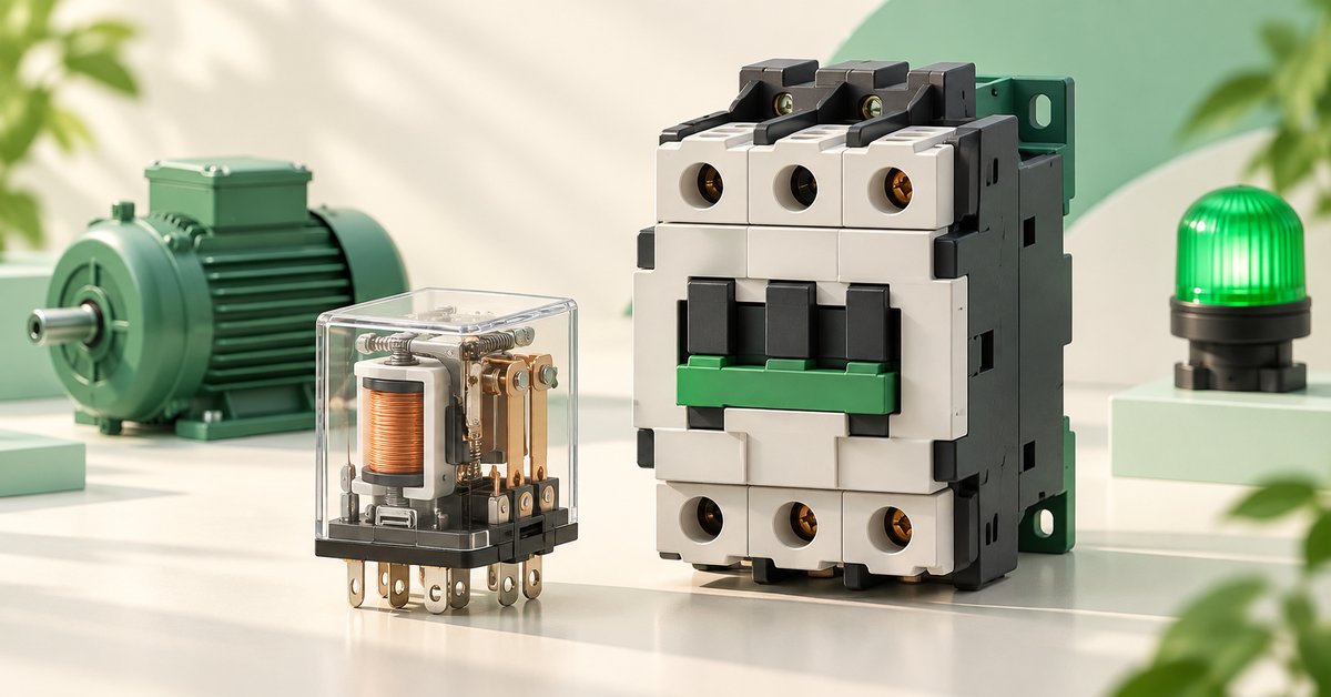
Contactors commonly switch power loads; interposing relays commonly handle signals and control logic. For actual selection, check the load, coil voltage, switching capability, and duty in the manufacturer’s documentation.
1. What is a contactor, and what is an interposing relay?
A contactor is an electrically controlled switching device. In a motor panel, it commonly opens and closes the motor supply path according to control-circuit commands.
An interposing relay transfers signals, provides additional contacts, or creates a logic step between a command and an actuator. For example, a signal energizes KA1, whose contact then allows power to the KM1 coil.
This article compares conventional electromagnetic contactors and interposing relays. Relay describes a whole family; overload relays, timers, solid-state relays, and latching relays are not all the same device.
2. Look at two electrical paths to see the difference
Suppose a run-permission signal energizes KA1. The control path may be: control supply → KA1 contact → KM1 contactor coil → supply return. Current through KA1’s contact in this branch feeds the KM1 coil.
In the power circuit, the supply passes through protection and KM1’s main contacts to the motor as designed. Energizing KM1 closes the main contacts. Motor load current passes through those contacts, not through the coil.
The coil and contacts belong to one device but do different jobs. The coil receives a command; the contacts switch another path. Coil voltage alone does not tell you what load the contacts can switch.
| Part being read | Question to answer |
|---|---|
| KA1 or KM1 coil | Which supply gives the command, and what coil voltage is required? |
| KA1 relay contact | Which signal, coil, or load is it switching? |
| KM1 main contacts | What load passes through, at what voltage and switching duty? |
| KM1 auxiliary contacts | Are they for holding, interlocking, or status feedback? |
3. Compare the job, not just the size
An interposing relay and contactor may share an electromagnetic principle but are designed for different tasks. A small relay is not automatically suitable for motor starting current; a large contactor is not an economical way to add a logic signal.
| Comparison | Interposing relay | Contactor |
|---|---|---|
| Typical role | Signals, logic, and extra control contacts | Switching motors or other suitable loads |
| Reading the drawing | Follow the coil and control contacts | Separate the coil, auxiliary contacts, and main contacts |
| What to verify | Load type, switching voltage/current, coil, and terminals | Load type, operating voltage, utilization category, coil, and protection coordination |
| Built-in overload/short-circuit protection? | Do not infer protection from the name interposing relay | A contactor alone does not replace protection devices |
4. Can a relay replace a contactor?
Do not answer yes merely because the current printed on the case appears sufficient. Carrying current and switching a particular load are different requirements. A resistive-load rating does not prove suitability for motor switching.
Nor should you assume every relay is limited to small currents. Power relays exist; for a specific load, check the manufacturer’s load ratings and conditions. What the device is rated to do matters more than its generic name.
Motor-contactor documentation includes utilization categories such as AC-3. Select using the table for the voltage and operating duty; do not use an AC-1 rating for a less inductive load as the motor rating.
The contactor switches; protection requires suitable devices and coordination. In a motor starter, an overload relay commonly acts on the control circuit to release the contactor; short-circuit protection must be considered separately.
5. Ask five questions before selection or a material takeoff
If the customer says only “control a pump,” you still lack enough data to choose a reference. Gather the information below before consulting the catalogue. This article does not prescribe one reference for every power rating.
For devices with suppressors, electronics, or polarized terminals, follow the coil wiring diagram. Do not assume every A1–A2 connection can be reversed.
- What is being switched: a motor, coil, resistive load, or signal?
- What are its voltage, current, or power and operating conditions? For motors, obtain the nameplate and starting method.
- Is the control supply AC or DC, and what coil voltage is needed?
- Are holding, interlocking, or status contacts required?
- Are there special switching-frequency, environmental, or protection-coordination requirements?
6. Try relay and contactor roles in a small circuit
In EleRun, test the command chain first without building the three-phase power circuit. Use a 24 VDC control supply and symbols with suitable simulation behavior, all on one page.
This shows which device commands which. It does not prove that real devices can switch the load or replace protection selection.
- Connect +24 V → maintained switch S1 → KA1 coil → 0 V.
- Connect +24 V → KA1 NO contact → KM1 coil → 0 V.
- Connect +24 V → KM1 NO auxiliary contact → H1 lamp → 0 V.
- Assign KA1 to the relay coil/contact pair and KM1 to the contactor coil/contact pair.
- Turn on S1 and trace KA1 picks up → KA1 NO closes → KM1 picks up → KM1 NO closes → H1 lights. Turn S1 off and compare the return states.
ELERUN LAB · TRY IT YOURSELF
Find the break in the KA1 → KM1 command chain
Build the three branches from the exercise on one page: S1 energizes KA1, a KA1 NO contact feeds KM1, and a KM1 NO contact feeds lamp H1.
- Change only the KA1 NO contact's tag to KA2; keep the KA1 coil's tag unchanged.
- Switch on S1 in Run. Predict the states of KA1, KM1, and H1 before checking the screen.
Compare your reasoning
S1 still energizes KA1. The contact now tagged KA2 no longer follows the KA1 coil, so the command chain to KM1 is broken and H1 cannot receive the command through KM1. Restore the KA1 tag and retest.
This experiment shows a signal link in the drawing. It says nothing about the real relay's load rating.
7. Frequently asked questions
Does a 24 V contactor coil mean it can switch only 24 V loads?

No. Coil voltage and contact ratings are separate specifications. A 24 V coil can belong to a device rated to switch a different voltage if that exact device’s documentation allows it.
Can an interposing relay replace an overload relay?
Not directly. An interposing relay transfers commands; an overload relay detects overload conditions according to its design. They may work together but perform different jobs.
8. Manufacturer references
- OMRON: relay principles and types
- Schneider: relays and contactors in control applications
- Schneider: AC-1 and AC-3 utilization categories
- Schneider: overload relays and contactor coil circuits
EleRun diagrams and exercises explain principles; they are not manufacturer-approved installation drawings.


