

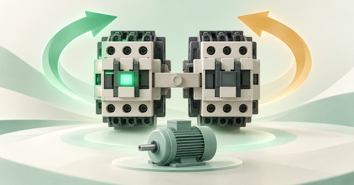
Forward coil KM1 passes through KM2’s NC contact; reverse coil KM2 passes through KM1’s NC contact. One energized side blocks the other. This exercise stops first, then selects direction.
1. Two directions, two supply paths
A reversing circuit controls a motor in two directions, such as a conveyor moving forward/backward or a mechanism extending and returning. With a suitable three-phase motor, swapping two phases reverses rotation.
Call the forward contactor KM1 and reverse contactor KM2. A contactor switches load power through a controlled coil. The power circuit determines phase order; the control circuit determines which coil receives power.
Build the control circuit with 24 VDC and compatible coils. You do not need a motor yet: observing KM1 and KM2 is enough to understand holding and interlocking. Forward and reverse are command names here; actual motion depends on wiring and machine mechanics.
2. Why is the other contactor’s contact in the supply path?
Recall NO, normally open before actuation, and NC, normally closed before actuation. Auxiliary contacts follow a compatible coil with the same device-linking tag.
The forward path passes through Stop, KM2 NC, the forward Start/holding branches, then KM1’s coil. While KM2 is released, its NC contact remains closed and allows forward starting.
Once KM1 picks up, its NC contact in the reverse path opens. Pressing reverse Start still cannot feed KM2. Likewise, KM2 blocks KM1. Using one side’s contact to block the other is electrical interlocking.
Each holding NO contact must bypass only its own Start button. Do not let it bypass Stop or the interlock; that would create an unintended supply path to the coil.
| Control branch | Path from +24 V to 0 V |
|---|---|
| Forward | +24 V → Stop NC → KM2 NC → (forward Start NO in parallel with KM1 NO) → KM1 coil → 0 V. |
| Reverse | +24 V → Stop NC → KM1 NC → (reverse Start NO in parallel with KM2 NO) → KM2 coil → 0 V. |
3. How do electrical and mechanical interlocks differ?
Electrical interlocking blocks a coil’s supply. Mechanical interlocking uses compatible mechanical parts to prevent both contactors closing together. They act in different places; NC contacts on a schematic do not prove a mechanical interlock exists.
In real reversing equipment, simultaneous closure can cause a phase-to-phase short circuit. Select contactors, mechanical interlocks, and wiring according to manufacturer documentation and machine design. Screen colors do not verify real assembly.
One easily missed point: NC interlocks alone do not define command priority when both Start buttons are pressed from rest. Do not assume forward always wins or two NC contacts resolve every scenario. The machine needs suitable simultaneous-command handling and interlocking.
4. Build each branch in EleRun, then combine them
If you understand Start–Stop holding, this is a manageable next step. Place the branches side by side to see which blocks which, and keep the whole exercise on one page.
Do not give both coils the same tag. Forward coil and contacts use KM1; reverse uses KM2. If a contact fails to follow its coil, inspect tags and symbol types before changing wires.
- Place the 24 VDC supply, Stop NC, two Start NO buttons, and KM1/KM2 coils. Each coil needs one holding NO and one NC blocking the opposite branch.
- Connect Stop on the common path before the branch split. Complete both supply returns.
- Build forward as in the table: KM2 NC in series before both forward Start and KM1’s holding branch.
- Build reverse with KM1 and KM2 exchanged. Check that each holding NO bypasses only the correct Start button.
- Start Run. Press and release forward Start; try reverse Start while KM1 holds. Then press Stop, release the Start buttons, and select reverse.
5. Five actions worth testing
This exercise changes direction by stopping and selecting again. In real equipment, a released coil does not mean a stationary motor: inertia may keep it turning. Machine design must determine when reversal is allowed.
Compare each action with the table. If it fails, stop Run before editing, change one thing, and retest from rest. Record actions the tool cannot directly reproduce as untested; another action is not a substitute.
| Action | Expected control-circuit result |
|---|---|
| Power on, no Start pressed | Both KM1 and KM2 released. |
| Press and release forward Start | KM1 picks up and holds; KM2 stays released. |
| Try reverse Start while KM1 holds | KM2 blocked by KM1 NC. |
| Press and release Stop with Start buttons released | Both coils released; no automatic restart. |
| From rest, press and release reverse Start | KM2 picks up and holds; KM1 blocked. |
6. Wrong behavior? Inspect the right branch before moving wires
If one direction works but the other will not start even after stopping, inspect the blocked branch’s NC interlock: correct type, tag, and endpoints? Then inspect Start, the coil, and its return.
If Start release stops it, inspect that side’s holding NO. If Stop fails, find a path bypassing it. If both coils energize, stop testing and trace both interlock branches; do not ignore it just because the motor picture still rotates.
Understanding means explaining a specific fact: “KM2 cannot pick up because KM1’s NC contact is open here.” Point to that contact. This is more useful than simply saying “the circuit is faulty.”
ELERUN LAB · TRY IT YOURSELF
Which direction loses its lock when one tag is wrong?
Build forward KM1 and reverse KM2 branches with holding and cross-interlock NC contacts on the same page. Start forward and release the button so KM1 remains energized.
- In a test drawing, change only the KM1 NC contact in the KM2 coil's path to a tag that has no matching coil.
- While KM1 is energized, what still blocks the reverse command? Compare with the drawing before the tag change.
Compare your reasoning
The NC contact no longer follows KM1, so the reverse branch loses its electrical cross-interlock. Both coils may be commanded if the other conditions allow it. Restore the KM1 tag and retest both directions, including Stop.
A drawing exercise does not replace a mechanical interlock or the machine's stop-before-reverse rule.
7. Frequently asked questions
Do I need to press Stop before changing direction?

In this exercise, yes: stop, release Start buttons, then select the new direction. Real machines may use other control methods but must account for speed, inertia, load, and switching capability; do not assume immediate reversal while rotating.
Can EleRun verify a real contactor’s mechanical interlock?
No. This exercise demonstrates supported coil/contact logic. Mechanical interlocking is part of real hardware and must be selected, installed, and checked against manufacturer documentation.
8. Manufacturer references
- Schneider Electric: electrically interlocked reversing control
- Schneider Electric: TeSys D mechanical and electrical reversing interlocks
EleRun diagrams and exercises explain principles; they are not manufacturer-approved installation drawings.


