

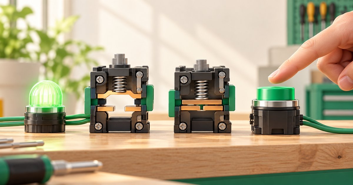
NO is open before actuation and closes when actuated. NC is closed before actuation and opens when actuated. “Closed” means the contact connects the path; the load still needs a supply and a complete return path.
1. What are NO and NC? Start with the resting state
NO means Normally Open; NC means Normally Closed. For a spring-return push button, consider it before pressing. For a conventional electromagnetic relay, consider it with the coil de-energized.
On actuation, the two types change in opposite directions. Pressing a NO button closes it; pressing a NC button opens it. In a relay, energizing the coil closes NO contacts and opens NC contacts.
“Normally” does not mean the state you see most often during operation. A machine may run all shift with its coil energized, but the contact is still named after its resting state.
| Contact type | Before actuation | After actuation |
|---|---|---|
| NO — normally open | Path open | Path connected |
| NC — normally closed | Path connected | Path open |
2. Does a closed contact mean power is present?
No. A contact connects or interrupts a path; it does not create power. If the supply is missing or the return path is broken, closing the contact will not light the lamp.
For a 24 VDC lamp example, trace the loop: +24 V → contact → lamp → 0 V. The lamp receives power only when the contact is closed and the entire path is correct. This is a DC control example; 0 V here is not protective earth.
So when a circuit fails, do not ask only “has NO closed?” Also ask “where does power come from, where does it travel, and how does it return?”
3. Why does Start usually use NO and Stop use NC?
In a conventional Start–Stop circuit, Start gives the run command. Its branch does not feed the coil until pressed. NO suits this behavior.
Stop sits on the common supply path. When released, NC lets the control path through; pressing Stop opens it and releases the coil. The holding branch must remain downstream of Stop so it interrupts both paths.
This is a basic control arrangement. A single NC button does not automatically make a compliant emergency-stop system. Emergency stopping requires assessment of the complete design and suitable devices.
4. 13–14 and 21–22: can terminal numbers identify NO/NC?
Terminal numbers can speed up reading when you know the device family. For example, Schneider’s TeSys D documentation identifies A1–A2 as the coil, 13–14 as an auxiliary NO contact, and 21–22 as NC.
Do not apply those numbers to every relay, socket, or changeover contact. Read the diagram on the device or documentation for its exact reference. Changeover contacts also have a common terminal and two possible paths; confusing the common terminal can change the circuit’s behavior.
For practice drawings, select the right symbol type first. A user-entered “NO” label does not turn a NC contact into NO; displayed terminal numbers do not create wire connections.
5. Use two lamps to remember NO and NC
This exercise uses a conventional electromagnetic relay, a maintained switch S1, and two lamps. A maintained switch retains its on/off position, letting you observe without holding a button.
Draw everything on one EleRun page. Assign KA1 to the coil and both auxiliary contacts with compatible simulation roles. H1 is fed through NO and H2 through NC. Each branch needs a complete supply and return.
- Coil branch: +24 V → S1 switch → KA1 coil → 0 V.
- H1 branch: +24 V → KA1 NO contact → H1 → 0 V.
- H2 branch: +24 V → KA1 NC contact → H2 → 0 V.
- Start Run with S1 off: predict H1 off and H2 on, then compare.
- Turn S1 on: the coil picks up; predict H1 on and H2 off. Turn S1 off and repeat.
| S1 | KA1 coil | H1 through NO | H2 through NC |
|---|---|---|---|
| Off | Released | Off | On |
| On | Energized | On | Off |
6. Unexpected result: where should you look first?
If the coil does not pick up, inspect S1’s branch and the coil return first. If it picks up but neither contact changes, inspect the KA1 tags and symbol types. If contacts change but the lamps behave incorrectly, trace each lamp branch.
Do not change the tag, contact type, and wiring together. Fix one thing and test again; you need to understand why the fault disappeared.
- Both lamps off: check the supply and return, then each contact state.
- H1 on from the start: check whether its branch incorrectly uses NC or bypasses the contact.
- Coil energized but H1 off: check whether NO has closed and whether wires actually attach to terminals.
ELERUN LAB · TRY IT YOURSELF
Swap one NO contact to see what NC means
Build the two-lamp KA1 exercise: H1 through NO and H2 through NC. With S1 off, predict H1 off and H2 on.
- In a test drawing, replace only H1's NO contact with an NC contact tagged KA1; leave H2's wiring unchanged.
- Before and after switching on S1, do the two lamps behave the same way? Why?
Compare your reasoning
With S1 off, both NC contacts are closed, so H1 and H2 have supply paths. When KA1 energizes, both NC contacts open and both lamps go out, provided their supply and return paths are complete. Restore H1's NO contact to get opposing states.
Do not merely relabel an NO symbol 'NC'; choose a contact type whose behavior EleRun supports.
7. Frequently asked questions
Are relay NO/NC contacts the same as push-button NO/NC contacts?

They use the same naming of states before and after actuation. What actuates them differs: you press a button, while an electromagnetic relay coil controls its contacts. Coil state does not explain every sensor or special device.
Is a NO contact always safer than NC?
You cannot decide from NO or NC alone. Behavior on power loss, wiring faults, contact faults, and the whole system’s stopping requirements determine the appropriate arrangement.
8. Manufacturer references
- Schneider: NO and NC contact states
- Schneider: NO, NC, and changeover contacts
- Schneider: TeSys D coil and auxiliary terminals
EleRun diagrams and exercises explain principles; they are not manufacturer-approved installation drawings.


