

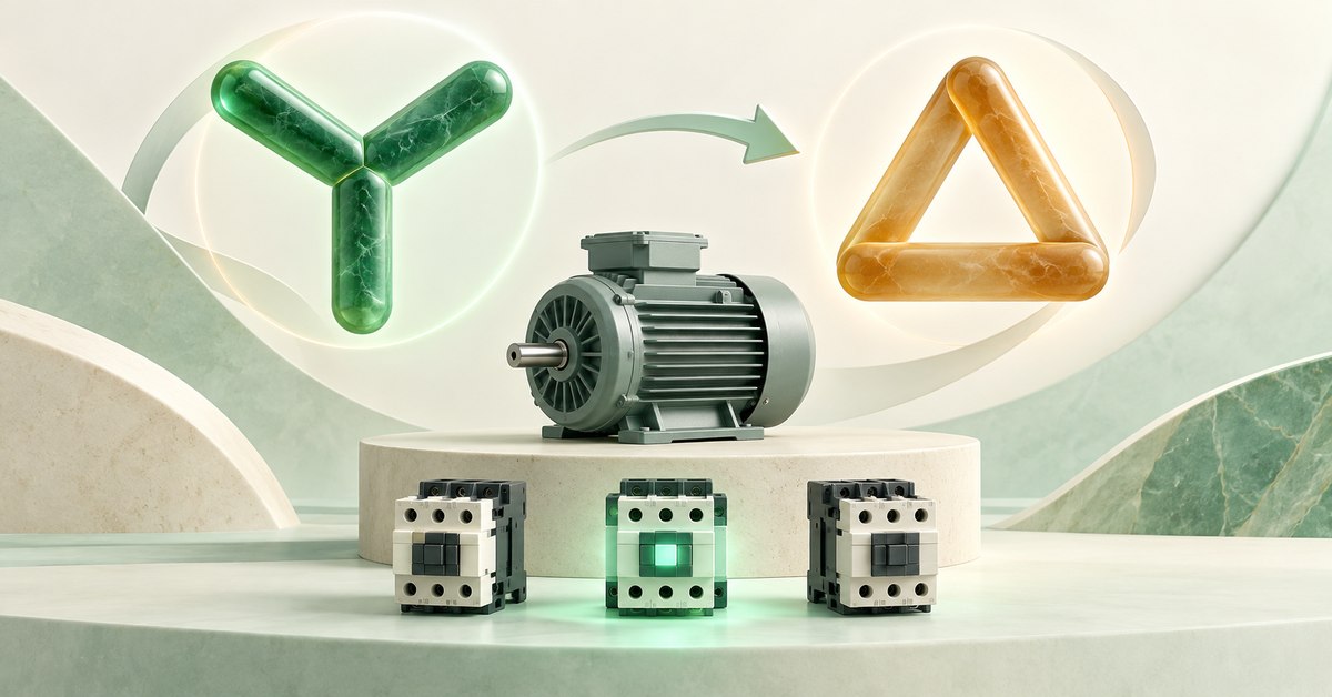
Start in star, open star, wait the appropriate transition interval, then close delta. Star and delta contactors must interlock. Star running time and transition time are different intervals.
1. Why start in star before changing to delta?
Star–delta starts some three-phase motors by changing winding connections. Initially the windings are connected in star (Y), giving each winding less voltage than delta on the same supply. Starting current falls, but starting torque falls too.
Once the motor reaches sufficient speed for the application, the circuit changes to delta (Δ) for suitable rated operation. This is not appropriate for every motor or load; a load needing high initial torque may be unsuitable.
Here we read the control sequence. You need not calculate current or choose contactor sizes to understand what closes first and what must open first. Device selection and power wiring require the motor data and manufacturer documentation.
2. Check voltage and winding leads, not just power
All six winding ends must first be accessible for reconnection. The delta-rated voltage must match the supply. Six leads alone do not prove suitability; motor type, load, and manufacturer guidance still matter.
On a 400 V three-phase supply, a Δ400/Y690 V nameplate indicates delta operation at 400 V. A Δ230/Y400 V nameplate indicates star at 400 V; it cannot be changed to delta at 400 V as in the first example.
Read the Δ and Y symbols beside each nameplate voltage. Do not memorize “large motor means star–delta.” Power rating does not tell you the voltage allowed across each winding.
3. Three contactors, three jobs
We name them by function: main KM supplies power, star KM makes the star connection, and delta KM makes delta. Other diagrams may use different KM numbers; follow the wiring and function rather than guessing from numbering.
Main KM stays energized in both star and delta. The other two operate alternately. The timer initiates transition, while interlocking prevents incompatible states.
Locate Stop and protection paths in the control circuit: a stop command or protection operation must release the relevant coils as designed. Turning off only the timer may not stop a contactor holding through another path.
| Stage | Main KM | Star KM | Delta KM |
|---|---|---|---|
| Not started | Released | Released | Released |
| Starting in star | Energized | Energized | Released |
| Transition interval | Energized | Released | Released |
| Running in delta | Energized | Released | Energized |
| Stopped as designed | Released | Released | Released |
4. Two easily confused time intervals
Star time allows acceleration while connected in star. Transition time is the interval after star opens and before delta closes. Waiting long enough in star does not automatically create a transition interval.
Real contactors need time to open their power contacts. A delta command arriving before star fully opens can cause a short circuit. Find both the star-release condition and the delta-permission condition.
Star KM’s NC belongs in the delta supply path, and delta KM’s NC in the star path. Real equipment also needs compatible mechanical interlocking and manufacturer-specified timing. One NO and one NC from an ordinary timer do not prove the required transition interval exists.
Do not take “5 seconds” or “10 seconds” from a tutorial as universal settings. Star time depends on motor/load acceleration; transition time depends on switching devices and the control arrangement.
5. Use EleRun to read states, then test each part
Begin with three coils clearly labeled by function. Compare with the state table. Before wiring the entire circuit, test holding, ON-delay, and interlocking individually to understand each role.
In EleRun, compatible supported coils and contacts link through matching tags. Keep tested sections on the same page. For a six-terminal motor, select the right symbol; an arbitrary motor picture does not provide the required terminal structure.
EleRun shows supported logic. A running motor picture does not provide actual starting current, torque, or acceleration time. Instantaneous screen transitions do not prove sufficient real contact opening time either.
A manageable exercise is to read a star–delta schematic and answer five questions. If you cannot identify the current path, isolate and test that part rather than adding more devices.
- When Start is pressed, which paths feed main KM and star KM?
- After Start is released, which contact holds main KM?
- At transition, what releases star KM?
- What blocks delta KM until star is open and the transition interval has elapsed?
- If Stop is pressed while waiting, does any path still feed a coil or hold the timer?
6. Three symptoms to investigate before testing further
Stays in star: check continuous timer activation, the selected function, and whether its output actually commands transition. Interrupted timer power may restart the interval.
Enters delta immediately on Start: check timed contact type, a zero setting, and any branch bypassing transition conditions. Do not lengthen time to hide an incorrect supply path.
Star and delta coils both powered: stop testing and inspect both interlocks and the transition sequence. Do not accept this state even briefly.
You can read the circuit when you can describe the order: start in star, star opens, transition wait, delta closes. Then point to the paths proving each step.
ELERUN LAB · TRY IT YOURSELF
Inspect the cross-interlock, not just the timer
On one page, place the main, star, and delta coils with their cross-interlock NC contacts as in the state table. Predict that star and delta must never receive commands together.
- In a test drawing, remove only the star contactor's NC contact from the delta coil's supply path; leave the timer unchanged.
- Which condition is now missing? If one normal Run sequence still looks right, does that prove sufficient interlocking?
Compare your reasoning
The delta path is no longer blocked directly by the star contactor's state. A normal-looking timer sequence does not prove the branch remains safe when conditions change. Restore the electrical interlock and verify the mechanical interlock and transfer sequence against the real equipment.
Make this change only in a simulation drawing. EleRun does not validate contact opening time, starting current, or a real starter's safety.
7. Frequently asked questions
Does star–delta reverse motor rotation?

That is not its purpose. Star–delta changes winding connections for starting and running. Reversing changes phase order to change rotation; these are different tasks.
Does a longer timer setting always improve starting?
No. Too short a star period may switch before sufficient acceleration; extending it does not fix an unsuitable load. Select timing for the motor, load, and switching equipment, not a universal duration.
Can this article be used as a panel wiring diagram?
It explains principles and sequence, not the complete power wiring, devices, protection, and settings for your machine. Those need separate design and verification.
8. Manufacturer references
- Schneider Electric: star–delta suitability and interlocking
- Schneider Electric: why star must open before delta closes
- ABB: interpreting star/delta nameplate voltages
EleRun diagrams and exercises explain principles; they are not manufacturer-approved installation drawings.


